Alkco Fixture Wiring Diagram

Wiring Diagram To Take Hot From A Receptacle For A Light 3 Way

Wiring Diagram Fan Light Source At The Fixture With Images

16 Exceptional Attic Remodel Stairs Ideas Light Switch Wiring

Stunning 4 Way Switch Wiring Diagrams Light In The Middle S

In The Three Way Switch Scenario Shown Above The Fixture Is
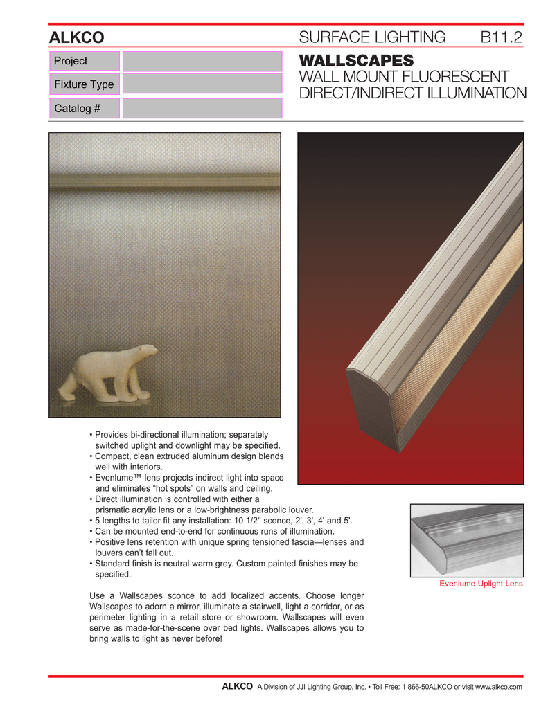
Alkco Surface Lighting B11 2 Wallscapes Wall Mount

About rexel billtrust.
Alkco fixture wiring diagram. The hot and neutral terminals on each fixture are spliced with a pigtail to the circuit wires which then continue on to the next light. Ul cul recognized component medical dental 60601 1. Assortment of fluorescent ballast wiring diagram. 0 10v dimming wiring diagram 0 10v dimmer switch leviton ip710 lfz or equal for other types of dimming control systems consult controls manufacturer for wiring instructions switched hot black switched hot red typical low voltage dimming wires purple gray typical electrical panel hot black typical 120v or 277v 60 hz neutral white.
It reveals the components of the circuit as streamlined forms and also the power and signal links in between the gadgets. For this application of fixtures for tube lights one socket will have the live power and the other socket will serve solely as a lamp holder. Changing the wiring on a fluorescent light fixture from series to parallel involves changing the ballast from a series to a compatible parallel ballast. The source is at sw1 and 2 wire cable runs from there to the fixtures.
Figure 3 optional rocker switch molex connector molex connector see wiring diagram on ballast for. Series ballasts can only be wired in series according to the diagram on the ballast. A wiring diagram is a simplified traditional photographic depiction of an electrical circuit. This diagram illustrates wiring for one switch to control 2 or more lights.
A low voltage wiring diagram will be supplied with the fixture and will match the specified control sequence. If a diagram cannot be found within this selection consult customer service. It reveals the components of the circuit as streamlined forms and the power and also signal links in between the gadgets. Multiple light wiring diagram.
Sometimes a specific lamp type is listed i e. If a lamp type is not listed the diagram shows a. A wiring diagram is a streamlined standard pictorial representation of an electric circuit. Install new tube and secure pins in socket with a 1 4 turn.
Parallel ballasts can only be wired in parallel according to the diagram on the ballast. The diagrams are categorized primarily according to the number of lamps in the fixture then followed by the ballast type. No power will be run to the other end the diagram below is for single end led t8 ballast bypass lamps. And its affiliated entities collectively rexel usa have contracted with billtrust a third party online payment processor in order to provide you with the convenience of online payments of invoices.
This is shown in the following image which features the led tube light connection diagram. Project information job name fixture type catalog number approved by.

Wiring Diagram Multiple 4 Way Switches Light Switch Wiring

Electrical Wiring Diagram Legend With Images Blueprint Symbols

Multiple Wires In 1 Light Fixture Junction Box Doityourself Com

Image Of Led Fluorescent Tube Wiring Diagram Rapid Led Wiring

How To Wire Two Light Switches With 2 Lights With One Power Supply

Lovely Wiring Diagram Fluorescent Light Switch Diagrams

Doorbell Wiring Diagrams Doorbell Diagram Doorbell Install
Image Result For Convert Outdoor Light To Outlet Outlet Wiring

Electrical Wiring Diagrams For Air Conditioning Systems Part Two

Electrical Outlet Symbol Floor Plan Symbols Electrical Symbols

Reflected Ceiling Plan Symbols Electrical Telecom With Images

An Ada Compliant Chart For Height Of Bathroom Fixtures Good

The Poor Man S Start Interrupt Switch Non Obvious Way To
