Allen Bradley Vfd Wiring Diagram

Allen Bradley Vfd Powerflex 4m
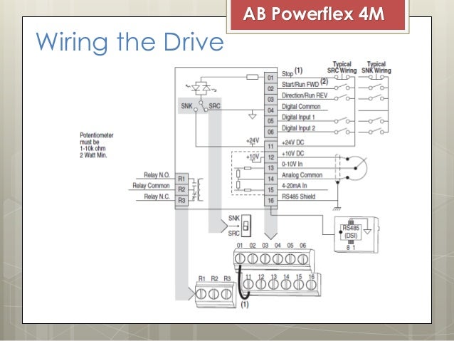
Ac Drive Vfd Allen Bradley Powerflex 4m

Powerflex 4 Wiring Diagram Kgv Breitewiese De

Allen Bradley Vfd Powerflex 4m 3 Wire Control Operation Youtube

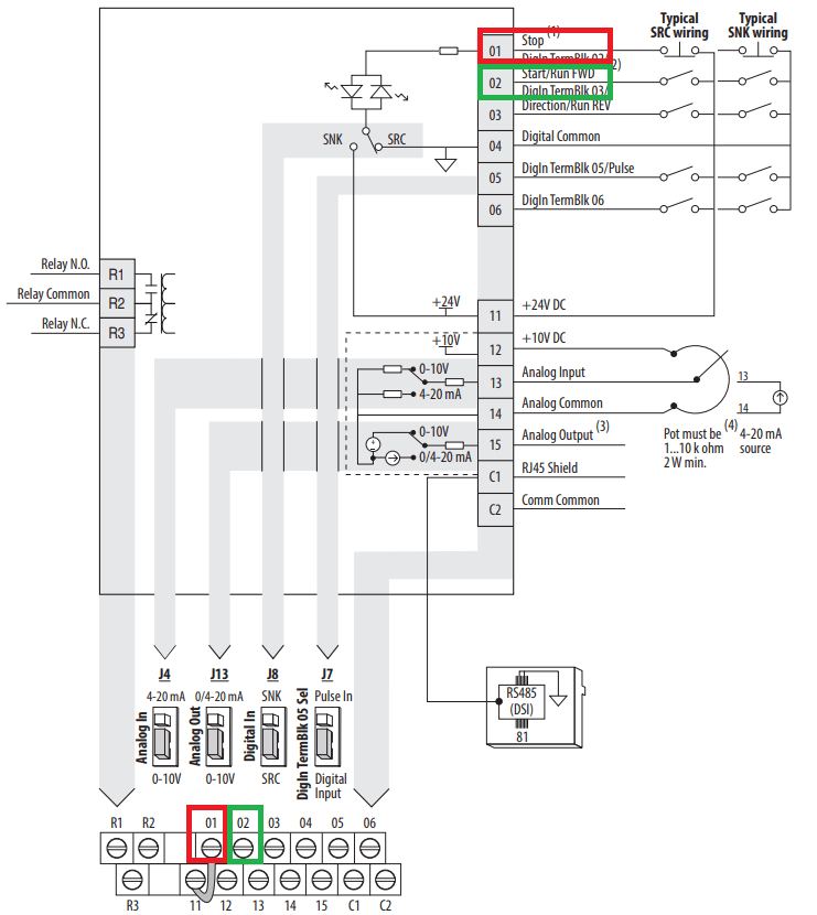
Powerflex 525 Vfd Setup Programming Parameters Wiring Diagram

Powerflex 4m Modbus Manual

Allen bradley powerflex 4m understanding vfd wiring this video explains the wiring of allen bradley powerflex 4m vfd its wiring fundamentals.
Allen bradley vfd wiring diagram. Our industry expertise helps deliver complete drive system solutions that maximize production and minimize risk. Drivetools connected component workbench and for your logix controlled applications use studio 5000 logix designer. Allen bradley drives technical support. Wiring diagrams ww introduction this booklet has been prepared as a guide to some of the useful ways allen bradley s manual and magnetic across the line starters may be applied.
An incorrectly applied or installed drive can result in component damage or a reduction in product life. Wiring or application errors such as. Parameter names will appear in brackets. They come standard with built in i o which is ideal for machine builders and system integrators who want to reduce engineering costs deliver machines to market faster and meet end user demand for more productive machines.
Explore the capabilities of our powerflex 525 ac drives through the powerflex 520 series virtual brochure and video. For allen bradley drives technical support. Select the tool that best fits your need. Powerflex 70 adjustable frequency ac drive.
Contact your local allen bradley distributor or rockwell automation sales representative. A human interface module him is required to perform the basic start up routine covered in this manual. Allen bradley powerflex manual online. It will also serve as a useful.
Power wiring 20 electronic motor overload protection 21 drive fuse and circuit breaker ratings 22. The wiring diagrams heavy lines. Learn how the information from our portfolio of intelligent motor control can position you to make better operating decisions improve. 6 rockwell automation publication 20b in019e en p july 2013 powerflex 700 adjustable frequency ac drive frames 0 6 product safety attention.
It show s how to connect external source of. Powerflex 753 ac drives are cost effective and easy to use in general purpose applications requiring safety features. The examples and diagrams in this manual are included solely for illustrative purposes. Manual conventions to help differentiate parameter names and lcd display text from other text the following conventions will be used.
The information provided is intended for qualified. Technical documentation contact your local allen bradley distributor or rockwell automation sales representative. Table 52 micrologix wiring diagrams discrete input and output voltage ranges.

B0d7e5e Ab On Vfd Wiring Diagram Wiring Resources

Allen Dley Vfd Wiring Diagram Wiring Diagram
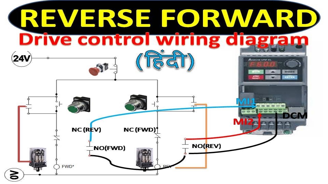
Vfd Forward And Reverse Wiring With Programming Logic Relay

Vfd Wiring Diagram General Wiring Diagram
Allen Bradley Plc Wiring Diagram Wiring Diagram

Plc Wiring Vfd Wiring Skills Hands On Electrical Training

Allen Bradley Vfd Start Stop Using Push Button 3 Wire Operation

Powerflex 4 Ac Drives

Ab On Vfd Wiring Diagram Wiring Diagram

Practical Machinist Largest Manufacturing Technology Forum On

Powerflex 4 Installation Manual

Powerflex 70 Ac Drives

Ab Microcontroller Wiring Diagram Wiring Diagram
