Allen Bradley Wiring Diagram Eye
37e63fd Allen Bradley Wiring Diagram Eye Wiring Library

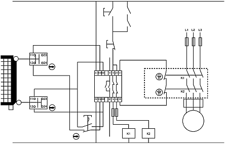
Wiring Diagram Contactor How To Wire A For 3 Phase Throughout

Allen Bradley Wiring Diagram Eye Wiring Diagram

How To Wire A Proximity Sensor To A Plc
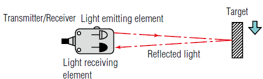
Photo Eye Sensor How To Wire A Photoelectric Sensor Into A

3 Phase Astronomic Timer

A wiring diagram gives the necessary information for.
Allen bradley wiring diagram eye. The wiring diagram dictates a standard configuration which requires a 24vdc and gnd signals for power. Our bulletin 888 dc micro m12 panel mount receptacles are die cast connectors ideal for use in enclosures or for creating custom wiring configurations. Wiring diagrams cable connections are shown in the following diagrams. To use this manual this manual is divided into two sections.
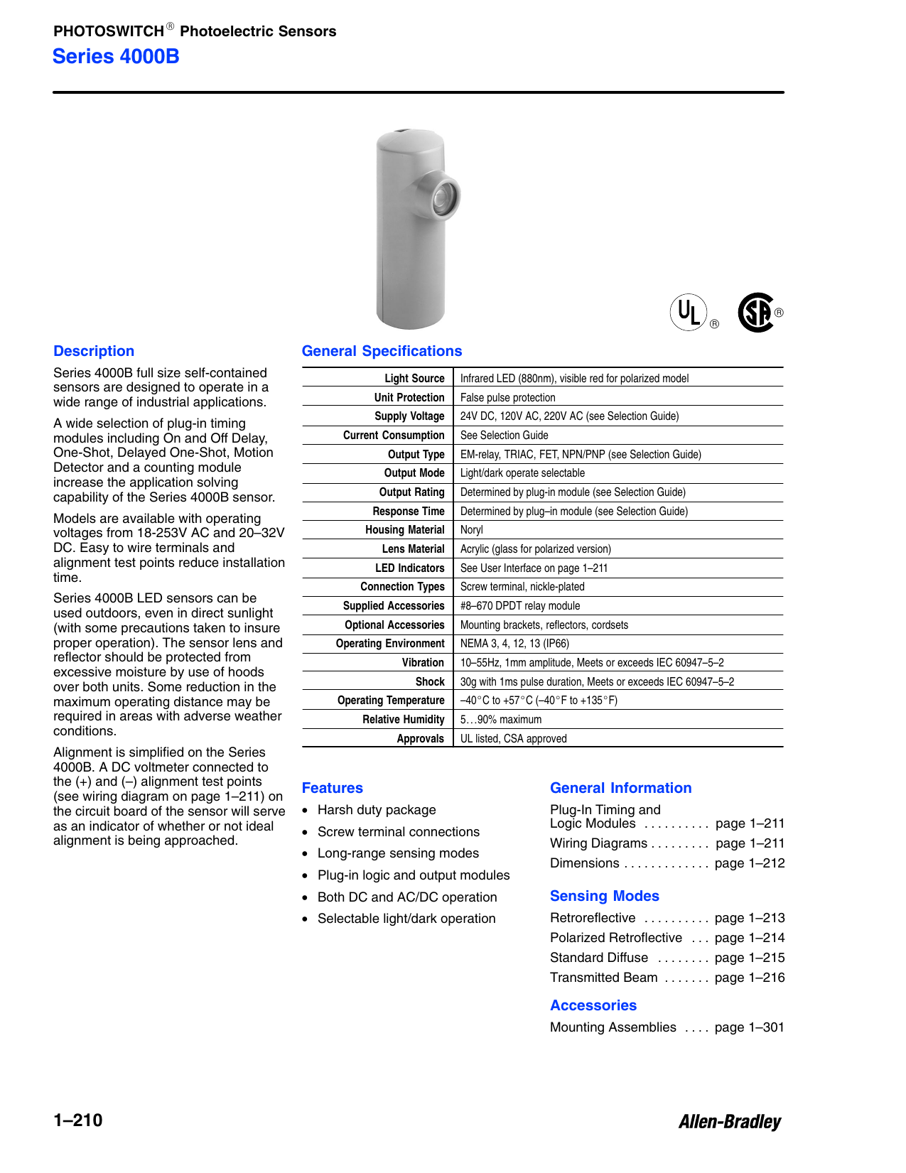
The wiring diagrams heavy lines. Use din rail mounting kit allen bradley 64 136. 42js visisight 4 3 1 2 3 2 1 4 m12male m8male brown 1 white 2 black 4 blue 3 load load lo do brown 1 do black 4 load load lo transmitted beam emitter brown 1 black 4 blue 3. Photoswitch series 5000 modular photoelectric sensors terminal style power base wiring diagrams mini quick disconnect wiring diagrams 42mtb 5000 42mtb 5001 42mtb 5002 42mtb 5003 42mtb 5004 l1 l2 42mrl photohead 120v ac 240 vac 48v ac dc 24v ac 24v dc l1 l 2 with em relay output module nc c no 120v ac 240v ac 48v ac dc 24v ac 24v dc.
Their modular design provides panel mount capability helps keep things neat and organized and allows simple replacement in areas where cables are likely to be damaged or replaced frequently. Cannot assume responsibility or liability for actual use based on the examples and diagrams. 9 0 qd 2 4 1 3 1brown 2white npn 4black pnp 3blue. 2 wiring diagrams all models except transmitted beam source 4white 3 1 2 4 4 pin dc micro qd model.
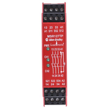
Any particular installation allen bradley inc. This series features a four turn sensitivity adjustment potentiometer and high speed dc models as fast as 0 2 ms. Wiring diagrams ww introduction this booklet has been prepared as a guide to some of the useful ways allen bradley s manual and magnetic across the line starters may be applied. The first section contains the plc i o module interface selection tables followed by the swing arm to photoelectric wiring diagrams.
Rightsight general purpose sensors. The sensor has two outputs that may be tied into a programmable logic controller input of the sinking type. These sensors take many of the features of larger solutions and puts them in a smaller more adaptable package to deliver excellent detection capabilities where size and shape matter. Our bulletin 42ef rightsight general purpose sensors are designed for light to medium level industrial use.
Pin numbers correspond to an m12 or m8 male connector on the sensor. Maximum nonhazardous area voltage must not exceed 250v. Division 1 installation wiring diagrams original instructions photoswitch photoelectric sensors series 5000 intrinsically safe catalog numbers 42dtb 5500 42dru 5500 42dru 5700 42drp 5500 42dra 5500. Series 6000 compact photoelectric sensors.
Series 6000 compact photoelectric sensors provide reliable general purpose sensing in a compact package.

1756 If6i Wiring Diagram

Series 9000 General Purpose Sensors

Allen Bradley Contactor Wiring Diagram Kuiyt 10balmoond

Cyclone Wiring Diagram Wiring Diagram

Photoelectric Eye Wiring Diagram Giant Fuse8 Klictravel Nl

Allen Bradley 1761 Cbl Pm02 Elec Intro Website
440r N23132 Allen Bradley Guardmaster Msr127tp 24 V Ac Dc Safety
Engineer On A Disk

Plc Ladder Logic Symbols Motor Control Circuits With Images
856t Control Tower Stack Lights Essential Guide Van Meter Inc

Precision Link System Installation Operation And Troubleshooting
100s C16ej23c 100s C 3p Safety Relays 24 V Dc 16 A 690 V Ac

Plc Wiring Vfd Wiring Skills Hands On Electrical Training
