Alliance Antenna Rotor Wiring Diagram

Vintage Alliance Tenna Rotor Electric Antenna Control Box For Tv

Vintage Alliance Tenna Rotor Neswn Model No T45 Antenna Rotor

Construction Of Dc Motor Electrical Engineering Motor

Calibrating Hd 73 Rotor Qrz Forums

Cde Rotator Parts Rotor Parts Com
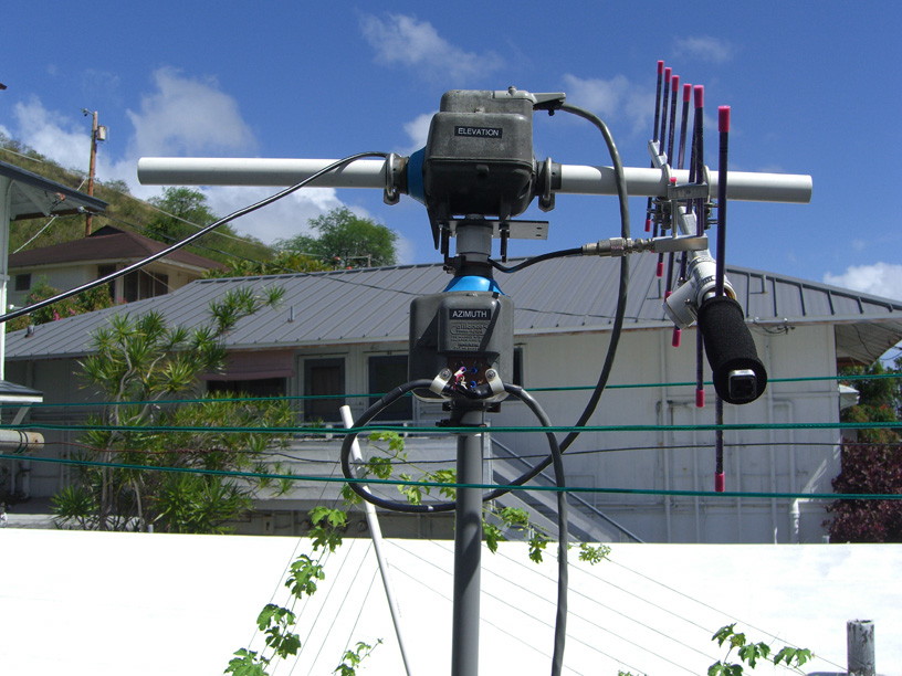
Az El Rotor Control
This could have been a reference to a 4 wire controller to a 3 wire rotor i wired 1 2 3 from the channel master mod 9524c output.
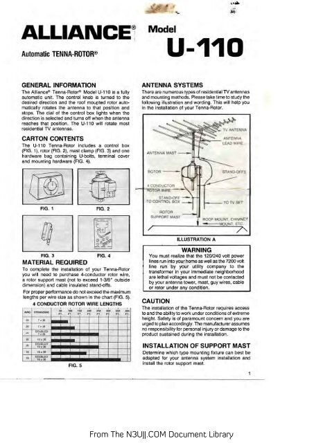
Alliance antenna rotor wiring diagram. Alliance u ioo general information model u ioo. The good news is that norm s rotor service has bought all parts all materials and all technical data from alliance. The control knob is turned to the desired di rection and the rotor automatically rotates the antenna to that position and stopss the dial lights up when the direction is selected and turns off when the antenna reaches that position. Tenna rotor t 10 antenna pdf manual download.
All channel master antenna rotors use 3 conductor rotor wire. Most rotor wire will be color coded. Look in you instruction manual to see what wire size to use for longer runs. The rotor unit which mounts on the mast below the antenna and the control box which is placed on or about the tv receiver these are interconnected by a four or five conductor cable.
15 complete routing of the antenna lead wire and rotor wire to the tv set per antenna manufacturer s instruc tions. 30v 3 amp 60hz. Tenna rotor u 83 tenna rotor k 22 tenna rotor u 98 tenna rotor t 20 tenna rotor k 22a tenna rotor u 100 tenna rotor t 45 tenna rotor t 12 tenna rotor. The alliance tenna rotor consists of two units.
View and download alliance u 100 service manual online. View and download alliance tenna rotor t 10 service manual online. An example if top of tower installation is usedand the antenna boom is mounted one foot above the rotator the wind pressure against the antenna could result in a bending moment of 300 pound feet. Alliance is out of the rotor business completely.
Antenna installation might be exposed. U 100 antenna pdf manual download. Stano ff antenna wire slack antenna lej owiae step 11 f ig. The alliance tenna rotor model u ioo is a fully auto matic unit.
Nrs now owns all rights to and a complete parts inventory for the hd 73 and u100 u110 series rotors and control boxes. To 1 2 3 then jumpered 3 to 4 on the alliance tenna rotor don t know what mod. The bad news is. Remove the bottom or access plate of the drive unit housing and attach the rotor wires.
If the same wind condition existed and the antenna was mounted 2 feet above the rotator the bending moment would. The theory of operation concerns two separate circuits. The rotor wire as shown. For runs up to 200ft you can use 22ga 3 conductor wire.

Tinware Candle Mold 6 Six Tube Wax Paraffin Wick Home Made Decor

Alliance Antenna Rotor Wiring Diagram Wiring Diagram

Pin By Kelly Finn On Cb Hamm Radios With Images Antenna

Cfm International Leap Petroleum Engineering Electric Jet

Td 7059 Rotor Wiring Diagram Together With Channel Master Antenna

1 Using Microcontrollers In Amateur Radio An Az El Controller
Antenna Rotor Wiring Diagram Wiring Diagram

Rotor Wiring Diagram Wiring Diagram
Ubm1wfqppheuqm