Imca Msd Wiring Diagram

Msd Ignition Wiring Diagrams With Images Diagram Msd Wire

Imca Msd Wiring Diagram Wiring Diagram

Kl 7344 Coil Ballast Resistor Wiring Diagram Msd 6al Wiring

Msd Ignition Wiring Diagrams In Msd Distributor Diagram On Msd
Msd Ignition Wiring Diagrams Brianesser Wiring Diagram

Zk 8986 Ignition Wiring Diagram Also Msd Ignition Wiring Diagram

Figure 5 wiring to a points or amplifier ignition with an msd 5 or blaster ignition using the points trigger.
Imca msd wiring diagram. The msd 5 and blaster ignitions are inductive designs and do not share. Collection of msd digital 6al wiring diagram. Wiring general wiring information wire length. 6a pn 6246 and the 6t pn 6446.
A special rev limit must be selected when connecting to the power grid. It shows the components of the circuit as simplified shapes and also the power as well as signal connections in between the tools. It shows the elements of the circuit as streamlined shapes and the power as well as signal connections in between the gadgets. All of the wires of the msd ignition may be shortened as long as.
Collection of msd ignition 6al 6420 wiring diagram. A wiring diagram to connect the msd power grid system controller to a 6al can be found in the instructions for the system controller pn 7730. Msd offers ignition controls for odd fire 6 cylinder engines. Msd tach adapter pn 8920 if your tachometer doesn t work correctly after installing an msd ignition control always try to connect the tach s trigger wire directly to the tach output of the ignition.
If the tach still registers incorrectly install this tach adapter. Gm ignitions wiring with an msd wiring harness. Harness pn 8877 1996 on gm vehicles. Msd was the first company to develop and offer the multiple sparking capacitive discharge ignition for engines.
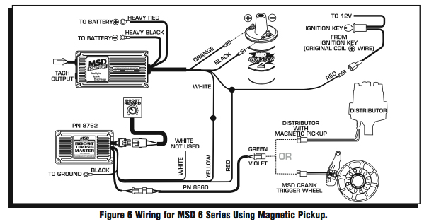
A wiring diagram is a simplified standard pictorial representation of an electrical circuit. A wiring diagram is a simplified conventional pictorial depiction of an electric circuit. Figure 6 wiring to points or amplifier ignition with an msd 6 series. Install the cover and screw.
To gray tach www street fire com. After cutting the loop s turn the wire ends away from each other so they cannot come into contact. Based in vinton iowa and sanctions classes of modifieds late models sprint cars stock cars and hobby stocks.
Imca Msd Wiring Diagram Wiring Diagram

Msd Ignition 6al Wiring Diagram Ignite Diagram Msd

Msd Distributor Wiring Diagrams Schematics Best Pro Billet Diagram

Msd Pn 6520 Wiring Diagram Diagram Msd Wire

Wiring An Msd With Diagram For 6al Distributor For Msd Distributor

Msd 6al Wiring Question Pelican Parts Technical Bbs With Images

Pin On Patrick Lothrop

Msd 8738 Soft Touch Rev Limiter Control For 6 Series

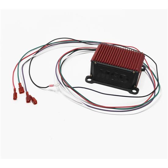
Msd 6530 Wiring Diagram Msd Diagram Heavy Red

The 2nd Generation Rx 7 Msd 6a Wired Up Msd
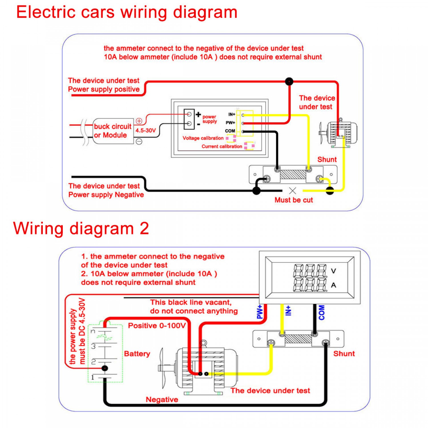
12v Amp Meter Wiring Diagram Wiring Diagram

Msd 82878 Multiple Spark Coil Set Of 8 Amazon Best Buy
Garage Sale Msd 8728 Soft Touch Rev Limiter Control For Hei
