Incremental Encoder Meter Wiring Diagram

Pin Su Incremental Encoders

Wiring An Incremental Rotary Encoder With Plc Youtube
Torin Drive International

Figure A 3 The Schematic Design Of The Incremental Encoder Part
Http Engineering Nyu Edu Mechatronics Control Lab Criag Craig Rpi Senactinmecha S A Optical Encoders Pdf

Pin On Witchert

Multi channel differential encoder wiring with commutation tracks can have up to 14 wires and miswiring can result in signal issues such as deformed pulses low signal amplitude and shorted.
Incremental encoder meter wiring diagram. Wiring diagram for ie58a incremental encoder ask question asked 3 years 10 months ago. Active 3 years 10 months ago. A wiring diagram is a streamlined traditional photographic depiction of an electric circuit. I cannot find a lot of information about the output voltage.
I have searched diagrams for it and it seems like it is hooked up correctly. Wiring diagrams are shown for zone 1 and zone 2 applications. Wiring optical incremental encoder. Assortment of heidenhain encoder wiring diagram.
My input for can be between 5 24v i have attempted to probe the output voltage with a meter and get 1v. Differential wiring needs two wires per channel that reference each other. Determining how to make 7 wire ac motor run without wiring diagram. That is the wires carry signals that are 180 out of phase.
Encoders provide motion control systems information on position count speed and direction. Refer to the wiring diagrams and pinout and phasing tables for specific information on each option. Encoder wiring schemes can be unique to each encoder and one should follow the diagram or pinout designated on the encoder datasheet. As the encoder shaft rotates output signals are produced proportional to the distance angle of rotation.
Figuring out wiring of optical encoder. The signal may be in the form of a square wave for an incremental encoder or an absolute measure of position for an absolute encoder. I have a question on wiring a 4 wire rotary encoder. Phase a channel typically leads phase b channel for clockwise shaft rotation.

Pin On Electrical Equipment Supplies
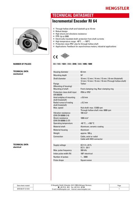
Technical Datasheet Incremental Encoder Ri 64
Https Www Tr Electronic Com F Tr V Pr Gb 0019


How To Use A Rotary Encoder In An Mcu Based Project Projects
Www Plcdirect Eu

Zapi Handset Programming Console Handheld Programmer For H0 H2b
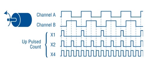
Quadrature Encoders The Ultimate Guide
Http Edge Rit Edu Edge P09503 Public Dgs20 Pdf
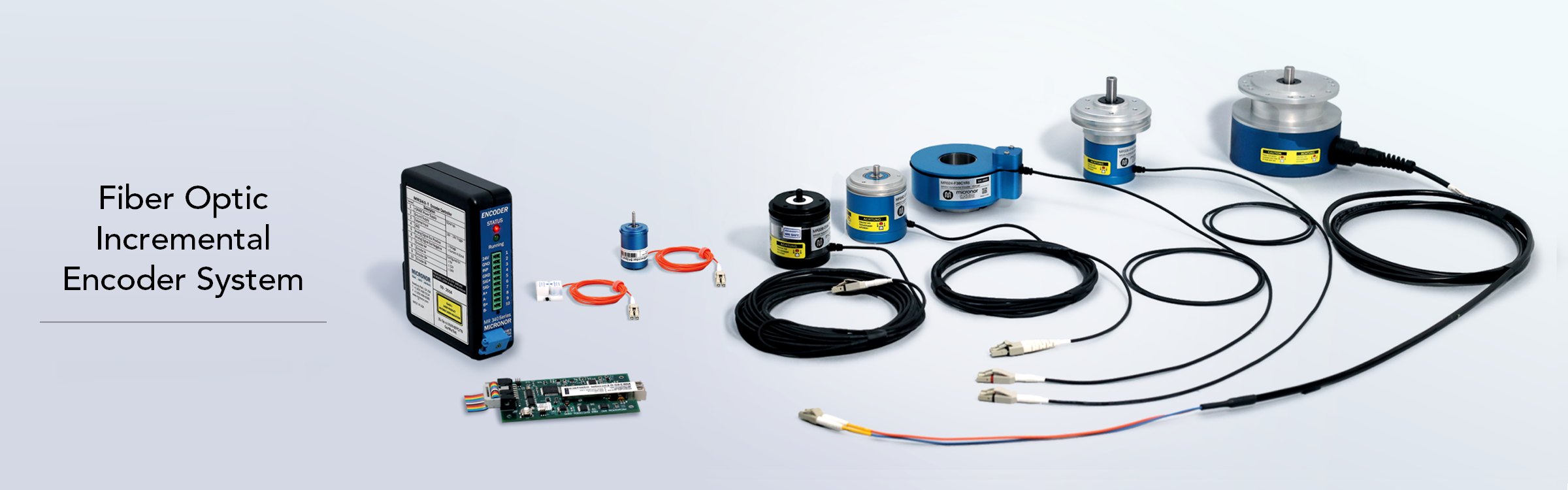
Mr340 Rotary And Linear Incremental Encoder Series Micronor
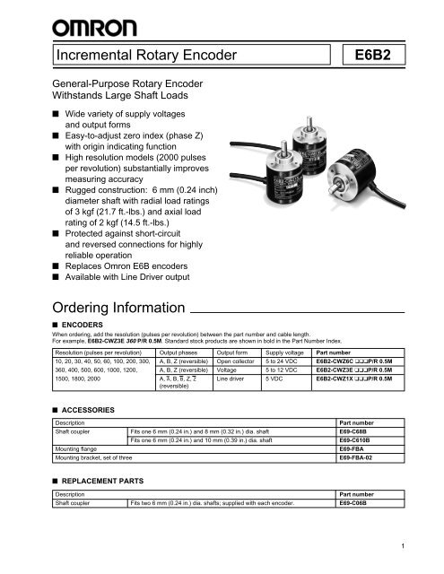
Incremental Rotary Encoder E6b2 Ordering Information

Dc Sepex Motor Xq 3 8 With Images Traction Motor Motor Golf

Rotary Encoder How To Debounce Them For Absolute Accuracy
